|
Advanced Thermal Management
Techniques for High Power Electronic Devices
The introduction of more
densely populated electronic processing systems
utilising high power processing chips with
heat fluxes up to 250Wcm-2 has caused the limits
of conventional forced air convection cooling
techniques to move towards their thermal limits
and a requirement for advanced thermal
management systems to dissipate in excess of
20kW per server cabinet in 3G and 4G systems has
emerged.
In collaboration with
Industry (Thermacore
Europe) a project is being carried
out to develop passive cooling systems using
two-phase heat pipe technology to transport heat
to a remote location where it can be dissipated
more easily using liquid cooling or enhanced
forced air convection techniques (fig. 1).
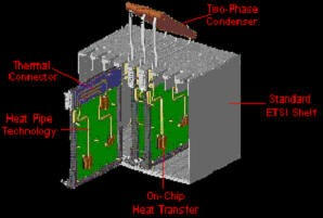
Fig. 1 - Forced air convection therma
bus
Minichannel Liquid Cold
Plates
An on-chip
minichannel cold plate prototype (fig. 2)
manufactured from 1.5mm thick, 42mm wide
Aluminium extrusion with 35 x Ø750µm circular
microchannels running through its cross-section
doubles the heat transfer surface area available
for forced liquid convection when compared to
the surface area of the flat plate.
Laminar flow investigations of water through the
channels found that the temperature of a
simulated chip could be maintained below the
specified maximum temperature of 70°C whilst the
chip power was able to be increased from 120W to
320W.
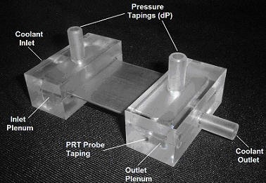
Fig 2
- An on-chip minichannel cold plate prototype
In heat pipes, the transport
of heat between the evaporator and condenser
sections is limited by opposing pressured of the
vapour and the returning condensed liquid.
Loop thermosyphons overcome this limitation by
having separate liquid and vapour lines to form
a loop. Flow of vapour and liquid
causes a circulation around the loop allowing
the fluids to to circulate in the same
direction, enhancing the performance of the
device. The industrial 'Therma BusTM'
project uses the LTS to transport heat from the
processing components to the rack level cooling
system. Figure 3 shows two LTS's
transferring heat from two processing chips to a
liquid cold plate at the top of the board.
The largest thermal resistances in this system
are across the thermal interface between the
chip and the LTS evaporator and from the LTS
condenser to the Liquid Cold Plate.
Loop Thermosyphon (LTS)
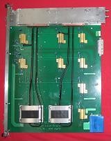
Fig. 3 - PCB with 2 x LTS and
Liquid Cold Plate
Combined Liquid Loop
Thermosyphon
By combining a minichannel
cold plate with an LTS to form a vapour to
liquid heat exchanger, a more compact system is
produced with a lower thermal resistance due to
the elimination of the thermal interface Layer
(fig. 4).
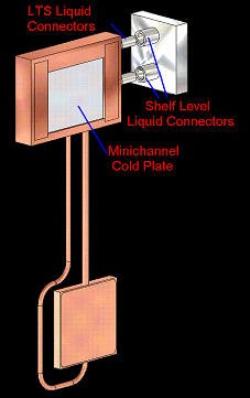
Fig. 4 -
Minichannel cooled LTS
For more information please
contact Dr Jon Lee
or Prof David Reay.
|